M-ZPM - free energy generator
Firstly, I should tell something about mysteriously sounding "M-ZPM". Term ZPM means "zero point module" and the letter "M" stands for "macroscopic". Some might find this name inadequate for this project, but in this way I wanted to honour great sci-fi series - Stargate.
This is updated article on this subject. There has been added pictures from simulation software. I'd like to present here some very simple idea of free energy generator. Its working principles were derived from high school course of electromagnetics and are comprehansible by any average minded person. You may reproduce, build, test and develop this project for your own domestic purposes. But if you plan to commercialize this you should let me know in order to obtain license. Since the invention and idea is a property of BIO-TEK, In legal terms the invention is under protection of Polish law even though it is not complete.
Overview of magnetic fields

 These schematics show permanent magnet with a wire perpendicular to the plane of your monitor. These lines and circles are represenations of magnetic field lines. Arrows show direction of these lines. As you can see, lines between poles of magnet are straight and lines around the wire are circular. If electric current in the wire were flowing from you in this arrangement the wire would be moved to the left. This phenomenon in wise books is called Laplace's Force. It is also called magnetic catapult or sling. This basic principle is used in all electric motors, dynamos, alternators and some other peculiar devices.
Why does it work like this? It is explained in the following way. Look at the arrows. On the right side of the wire we have lines going down all in the same direction. It means that at this area of space fields sum up. On the left side, lines of permanent magnet are at the opposite direction to field lines of wire. Consequently they weaken eath other. So on the right we have stronger field than on the left. This creates imbalance. Nature aims to ideal balance. So the wire is pushed to the weaker field in order to restore homogenousity. Of course if wire was fasten tight to something, the permanent magnet would move. But it would move in the opposite direction - to the right. It is worth to notice that the top and bottom lines of the wire do not contribute to movement because they are perpendicular to field of permanent magnet and such fields do not react. Actually this is not true, they react, but the top reacts precisely in opposite to the bottom, so they tend to twist the wire, because it is a pair of forces.
Approaching to free energy apparatus
In any motor in order to get force or work you must supply electric current. If one supplies current one obviously use out energy. You exchange electric energy for movement (and heat). Strictly speaking, one provides energy by means of electric current. One cannot "use out" energy nor current but only convert it into another form and finally dissipate it in space. This last sentence is for blockhead grumblers to satisfy their vain. But let's leave them alone!
 Now I can ask how we could build device which would without any doubt produce free energy. The best thing to do is elimination of the electric current conductors from this arrengement. Instead of them we will put another permanent magnets. This is the only way to achieve free-energy state without any scams. All right then. Bot how we can replace a wire coducting electric current with magnet? We know that the magnetic field of the conductor is somewhat different from the field of permanent magnet. This is shown at the left. As one can see, permanent magnet of any kind creates lines at both sides pointing at the same direction. This is contradiction to the field lines of conductor (wire) where lines on both sides point in opposite direction!
The solution to this problem is relatively simple. You must take two magnets and arrange them to form "checker". These below pictures show this clearly. The left one is a schematic view and the right one is view of simulation by proffessional software.
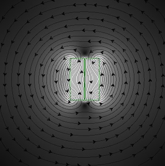
Omitting top and bottom field (which do not contribute to the force as it was said), we can see that the field of this arrangement is very similar (but not exactly the same) to the field produced by the wire. So we have grounds for replacing conductor with the set of permanent magnets. But this solution doesn't provide complete structure for generator. If you look closer to first schematics you will notice that wire will be pushed out from the magnet's field. If it is thrown out it won't be admited to get into field again, because the fields repel each other! In real life motors and alternators, the electric current in wires is changing direction or stops flowing. But we cannot do this with permagnet magnet. We can't swap poles inside of the magnet nor make them disappear. It seems that we approached to the dead end. Fortunately, there is simple solution for this. Look again at first schematics and think. Do not hurry. This text and problem won't run away. We know that local i.e transient amplification and weakening of the field causes imbalance which in turn makes the whole device move. We cannot allow the checker-magnets to leave the inner field, i.e. field of these big permanent magnets! The small ones must sit in that field forever. But magnets must move. We must create the path where these magnets will be moving. The path should be endless or infinite. Endless path? Yes, the circle is exactly that kind of path because it does not have beginning nor end. So, the big permanent magnet must be circular i.e. of ring or cylindrical shape. There may be two cylindrical magnets. The last schematics show complete arrangement. The lower ones show side view and computer simulated magnetic field with a plot with strenght of this field.
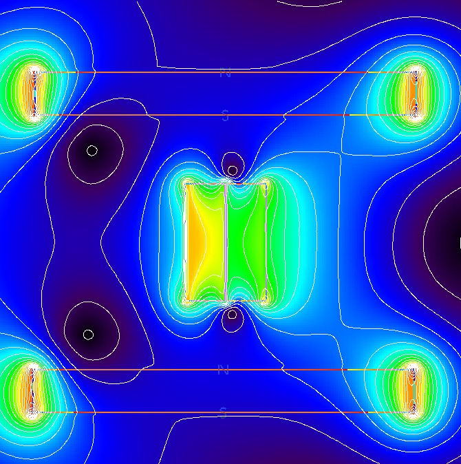
In this case checker-magnets are fixed mounted and the parts which are moving are two big permanent magnets.
Prototypes, tests and conclusion
The prototype of this device was built in the begining of 2007. It was partial success. The magnets are rotating only 180 degree. Why does this fixture not work? I am not sure. There are many possible reasons. Omitting the principle which bans all perpetual motion devices I can point at some causes:
- ring magnets used inhere might be magnetized nonuniformly since they were taken out of old loudspeakers and stored in Earth's magnetic field
- big magnets might require special directional magnetization
- there are some phenomena not taken into account which complicate or even prevent device to work at all
I hope some day the solution will be found and we all will gain benefit of free and clean energy. Maybe YOU could help?
Related material
Dr. Jaynes's website about free energy
Issued on home page: 25th May 2007
Updated: 11th April 2008
English translation: text genuinely written in English